 |
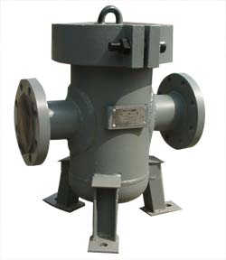
Type LPG Filter is a certain kind of complementary equipment that petrol, chemistry and other industries who are using flow instruments have to procure.
The filter working with the flow instruments can clean off impurities, misled objects liquid contains so as to ensure the flow instrument measuring accuracy and prolong its lifetime of usage.
This company provides many different versions of Filter with wide range of specifications and newly-developed-structures. Safety, reliability and other advantages like easy-in-using, quick-mounting /dismounting make the time consuming for cleaning minimized, labor intensity reduced and gain economically achieved.
Product Standard£ºQ/YXBM 838-1996
Main Technical Specifications
Type
|
DN
(mm)
|
PN
(MPa)
|
Mesh Count
|
|
Liquid |
Gas |
LPGX-15I |
15 |
1.6£¬6.3 |
40
|
|
0¡«120
|
LPGX-25I |
25 |
1.6£¬6.3 |
100
|
LPGX-40I |
40 |
1.6£¬6.3 |
LPGX-50I |
50 |
1.6£¬2.5 |
LPGX-80II |
80 |
1.6£¬2.5 |
20
|
LPGX-100II |
100 |
1.6£¬2.5 |
LPGT-40A |
40 |
1.6
2.5
4.0
6.3
|
|
LPGT-50A |
50 |
LPGT-80A |
80 |
LPGT-100A |
100 |
LPGT-150A |
150 |
LPGT-200A |
200 |
10
|
LPGT-250A |
250 |
LPGT-300A |
300 |
NOTE£º1) Mesh count can be changed as per user¡¯s request
2) For the temperature above 120¡æ , please specify for special order |
Type Code
|
Dimensions & Installation Reference
¡€¡ñThe Dimensions & Installation Reference of LPGT Upright Barrel Filter
¡ñThe Dimensions & Installation Reference of LPGX Tilting Plug Filter
|
 |
|
 |
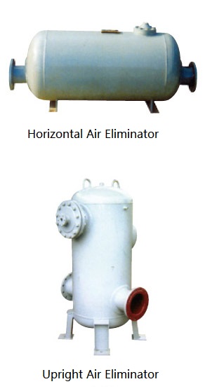
There are two styles for type LPX Air Eliminator, Horizontal one (type LPXF) and Upright one (type LPXL). The Eliminator works together with Flow Meter as an auxiliary equipment that is used to separate and eliminate gases contained within the liquid to be measured, because in most cases, liquids contain gases with different extent.
The measuring accuracy of the flow meter could be affected if such gases are also passing through the meter. Consequently, Air Eliminator is one of the essential components in flow measuring system, especially in the high-accuracy system.
Main Technical Specifications
DN
(mm) |
Max. Flow
m^3/h |
Nominal Pressure
MPa |
Medium Temperature
¡æ |
Medium Viscosity
mPa.s |
Max. Pressure Loss
MPa |
50 |
25 |
|
0¡«120¡æ
|
3¡«150
|
0.07
|
80 |
60 |
100 |
100 |
150 |
250 |
200 |
400 |
250 |
600 |
300 |
1000 |
350 |
1600 |
Note:1¡¢ Temperature above 120oC needs special order
2¡¢PN4.0MPa¡¢6.3MPa needs special order |
Type Code
|
| Dimensions & Installation Reference |
|
¡€¡ñDimensions of Horizontal Air Eliminator
¡€¡€¡ñDimensions of Upright Air Eliminator
¡€¡€¡€¡ñDimensions of flanges
Installation
Air Eliminator should be arranged in the up-stream of the Filter and Flow Meter, and located as close as possible to the Flow Meter. Before installation, pollutant, trash and welding residue within the pipelines must be washed off. In the mean time, arranging a by-pass pipeline is necessary. Please refer to the regular arrangement shown on Fig as follow.
Note:
| 1. For the safety reason on the job-site, any gas exhausted from the Eliminator must be transferred through certain exhaust pipeline into a specially-made container located in safe place; it is strictly inhabited to exhaust the gas directly in the room. |
| 2. To improve the working performance of the Eliminator, it is necessary to install a back-pressure valve on the outlet of the flow measuring pipeline or escalate the related pipeline above a certain height, either of which develops a back-pressure ranging from 0.015 MPa to 0.03 Mpa. Range of the back-pressure to be taken depends on liquid status, but it is generally taken as 0.022MPa. The pipeline escalation height can be calculated by the following formula: |
| h=2.2/r |
| where£ºh --- pipeline escalation height(m) |
| r ---- density of the liquid to be measured(g/cm^3) |
|
|

