|
LHS Helix Flow Meter (hereinafter referred to as Flow Meter) is mainly used in flow measuring for crude oil with high sand or water content, waste water with oil, Diesel, gasoline, light oil and other chemical materials; its components are made of stainless steel, axis and bearings are made of friction-endurable materials with high anti-corrosion and friction-endurable performance.
Features:
1. Helical Rotor: it allows accurate measuring of fluids with wide range of viscosity while minimizing the affection of wax or other viscose substances.
2. Stainless Steel Measuring Components: made of stainless steel to avoid the severe corrosion to the Meter caused by high water or other corrosive contents.
3.
Robust Bearing System with friction-endurable materials: this design ensures the prevention of the bearing damage from sand or stone.
4.
In case of its rotating parts stall, fluid will still pass through the Flow Meter without causing any sudden pipe pressure increasing due to blockage.
5.To meet the user��s requirements the Flow Meter can be equipped with different flow convertor that provides with optional Reading modes so as to comfort the user, meanwhile it also delivers pulses or standard electrical current signals (with extra options) that might be sent to the remote display instruments or computers for data processing.
6. exquisite structure, easy installation
LHS Flow Meter normally goes with different flow convertors as per user��s needs for the assigned purpose :
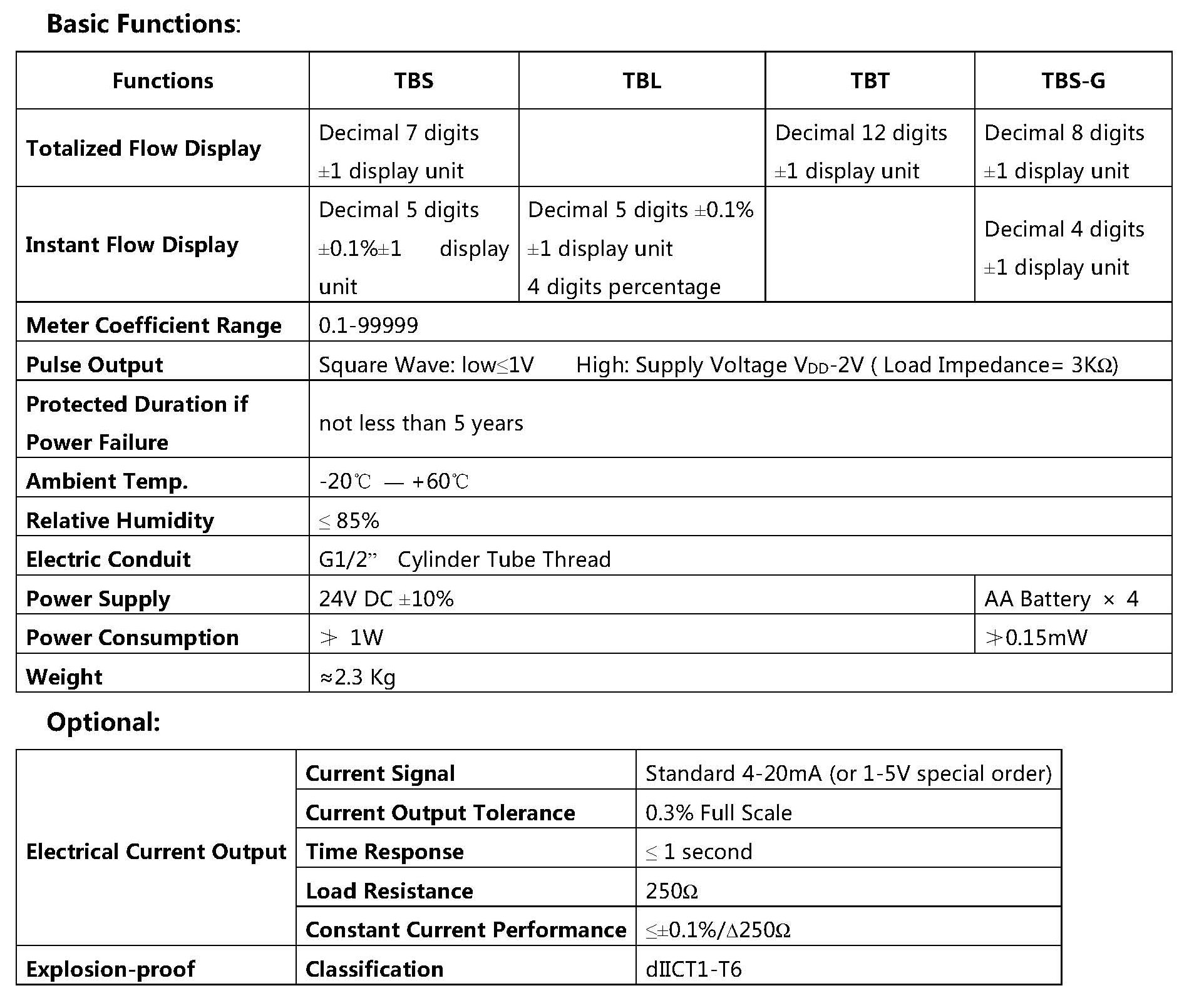
- TBS Flow Convertor: on-site instant flow rate LCD Display (5-digits); totalized (7-digit)
- TBT Flow Convertor: on-site totalized flow LCD Display (12-digits)
- TBL Flow Convertor: on-site instant flow rate LCD Display (5-digits); flow in percentage (4-digits-LCD display)
All above can be equipped with optional standard DC electrical current
signal output (FI Flow Convertor)
- TBS-G Flow Convertor: with self-power-supplier, on-site instant flow rate LCD Display (4-digits) and totalized (8-digits)
The Flow Convertor is of power failure data protection, stable, reliable accurate, less power consumption performance, and it is also easy to maintain, use and operate without tight restrictions to its up/down -stream straight pipe line conditions
Product Standard : Q/TDSM 12-2014
Verification Regulation : JJG 1037-2008 Verification Regulation of Turbine Flowmeter |
Working Principle & Structure
While fluid forces the helical rotor attached on the glossy axis rotating, the vane of the rotor swipes the detector, which in turn, generates electrical pulse signal. Within certain flow range, the number of pulse is proportional to the flow.The flow convertor processes andcalculates the electrical pulse signal,displaying the flow of fluid through the pipeline.
The structural scheme is shown on the right
|
|
Technical Specifications
1.Measuring Part
|
2��Flow Range |
Measuring Medium |
Crude oil with high sand and water contents; waste water with oil, Diesel, gasoline, light oil, other chemical raw materials |
Medium Viscosity |
0.3��400mPa��s |
Medium Temperature |
0��300�� |
Nominal Diameter |
25��250 mm |
Nominal Pressure |
PN1.6��2.5��4.0��6.3��
2.0��5.0MPa |
Flow Range |
1.2��1200 m3/h |
Accuracy class |
0.2��0.5��1.0 |
Materials |
Body |
Stainless Steel 1Cr18Ni9 |
Rotor |
Stainless Steel 2Cr13 |
Bearing |
Carbide YG6X |
Flange Standard * |
JB/T75-1994��GB/T9112-2000 |
Mounting Type |
Horizontal Piping |
|
DN
��mm�� |
Max Flow
(m3/h) |
Limit of Error |
Range Ratio |
3��1 |
5��1 |
10��1 |
25 |
12 |
��0.2% |
��0.5% |
��1.0% |
40 |
25 |
50 |
50 |
80 |
120 |
100 |
180 |
150 |
350 |
200 |
600 |
250 |
1000 |
|
|
* User��s request for Special Flange is negotiable. |
3��Flow Convertor |
| |
|
| |
Type Selection
|
|
Project and Content |
Code |
Example |
Helix Flow Meter |
LHS- |
|
|
|
|
|
|
|
|
|
LHS |
DN��mm�� |
25
(32)
40
50
(65)
80
100
(125)
150
200
250 |
25
32
40
50
65
80
100
125
150
200
250 |
|
|
|
|
|
|
|
|
100 |
Feature Code (Bearing) |
Regular(Carbide Bearing)
Others: on user��s request |
A
Z |
|
|
|
|
|
|
|
A |
Material (Rotor) |
Stainless Steel 2 Cr13
Duplex Stainless SteelSUS329J1
Others: on user��s request |
0
1
9 |
|
|
|
|
|
|
0 |
Nominal Pressure |
PN1.6
PN2.5
PN4.0
PN6.3
PN2.0
PN5.0 |
A
B
C
D
E
F |
|
|
|
|
|
B |
Accuracy class |
0.2
0.5
1.0 |
2
3
4 |
|
|
|
|
3 |
Output |
None
Pulse signal
4--20mA standard current
RS485 |
A
B
C
D |
|
|
|
C |
Display |
No on-site display
On-site instant flow and numerical percentage (TBL)
On-site flow totalized (TBT)
On-site instant flow & flow totalized (TBS)
With Self-power Supply; on-site instant flow & flow totalized (TBS-G) |
0
1
2
3
4 |
|
|
3 |
Explosion-proof |
None
Explosion-proof��d��CT1��T6�� |
/D
|
|
|
Special Flow |
Special flow |
�����
������ |
-90 |
|
| |
Example:
LHS-100A0B3C3-90 means Helix Flow Meter with nominal diameter DN100mm, pressure PN2.5MPa, accuracy class 0.5, output 4-20mA standard current, display on-site instant flow rate and flow totalized (TBS), non-explosion-proof, maximum flow 90m3/h |
Dimensions & Installation Reference
|
|
|
DN
(mm) |
L
(mm) |
H
(mm) |
W
��kg�� |
DN25 |
260 |
154 |
��7 |
DN40 |
300 |
162 |
��12 |
DN50 |
360 |
167 |
��16 |
DN80 |
460 |
182 |
��25 |
DN100 |
500 |
192 |
��33 |
DN150 |
650 |
215 |
��54 |
DN200 |
700 |
242 |
��84 |
DN250 |
1000 |
267 |
��138 |
* ������PN1.6���㣬�����������ϸ��ݷ��������仯�� |
|
|
Dimensions of flanges |
DN |
PN |
D |
K |
N-��L |
DN |
PN |
D |
K |
N-��L |
DN25 |
1.6
2.5
4.0 |
��115
��115
��115 |
��85
��85
��85 |
4-��14
4-��14
4-��14 |
DN100 |
1.6
2.5
4.0 |
��215
��230
��230 |
��180
��190
��190 |
8-��18
8-��23
8-��23 |
6.3
2.0
5.0 |
��135
��110
��125 |
��100
��79.5
��89.0 |
4-��18
4-��16
4-��18 |
6.3
2.0
5.0 |
��250
��230
��255 |
��200
��190.5
��200.0 |
8-��25
8-��18
8-��22 |
DN40 |
1.6
2.5
4.0 |
��145
��145
��145 |
��110
��110
��110 |
4-��18
4-��18
4-��18 |
DN150 |
1.6
2.5
4.0 |
��280
��300
��300 |
��240
��250
��250 |
8-��23
8-��25
8-��25 |
6.3
2.0
5.0 |
��165
��130
��155 |
��125
��98.5
��114.5 |
4-��23
4-��16
4-��22 |
6.3
2.0
5.0 |
��340
��280
��320 |
��280
��241.5
��270.0 |
8-��34
8-��22
12-��22 |
DN50 |
1.6
2.5
4.0 |
��160
��160
��160 |
��125
��125
��125 |
4-��18
4-��18
4-��18 |
DN200 |
1.6
2.5
4.0 |
��335
��360
��375 |
��295
��310
��320 |
12-��23
12-��25
12-��30 |
6.3
2.0
5.0 |
��175
��150
��165 |
��135
��120.5
��127.0 |
4-��23
4-��18
8-��18 |
6.3
2.0
5.0 |
��405
��345
��380 |
��345
��298.5
��330.0 |
12-��34
8-��22
12-��26 |
DN80 |
1.6
2.5
4.0 |
��195
��195
��195 |
��160
��160
��160 |
8-��18
8-��18
8-��18 |
DN250 |
1.6
2.5
4.0 |
��405
��425
��445 |
��355
��370
��385 |
12-��25
12-��30
12-��34 |
6.3
2.0
5.0 |
��210
��190
��210 |
��170
��152.5
��168.5 |
8-��23
4-��18
8-��22 |
6.3
2.0
5.0 |
��470
��405
��445 |
��400
��362.0
��387.5 |
12-��41
12-��26
16-��29.5 |
|
Installation & Wiring |
1��To install the Flow Meter
��1��Flow Meter should be installed horizontally.
��2��Flow direction within the pipe should be in accordance with the direction indicated on the Meter nameplate.
��3��Any valve for the flow adjusting purpose should be arranged at the Flow Meter downstream.
��4��The inner diameter of flow pipe should match the Flow Meter nominal diameter, and must be concentric with each other.
��5��Be sure, do not stretch the sealing pad into the pipe inner area when attaching. |
2��Flow Converter
��1�� Mount the Flow Converter on the Flow Meter housing by M14��1 Screw. Put the Converter on the connection pad of the housing, rotate it into the pad manually , then fasten the lock nut finally.��
��2��Explosion-proof sealing connection Fix the explosion-proof connector, and wiring as per Chapter 7 of this manual
��3�� Wiring
The Flow Converter wiring depends on different output as shown below: |
|
| |
��4�� Ground connection :
When shielded-cable is used, the cable shall be connected to the ground at a terminal, where usually Flow Totalizer is located; please to minimize the AC power noise that interferes the output signal cable, such cable should be apart from Power lines as far away as possible.
Note: Wiring is always carried out at the time of power off; correct wiring saves Flow Converter from damaging |
Key Points to the Installation of Explosion-Proof products |
This product can be used at certain hazardous areas which are stipulated by the following criteria of China:
GB 3836.1-2010 ��Explosive atmospheres �D Part 1 : Equipmen t�D General requirement �� & GB 3836.2-2010 ��Explosive atmospheres �D Part 2 : Equipment protection by flameproof enclosures "d"' , both of which are describing the environment like this :Explosion Class II, Grade C, Natural Temperature T1-T6 Group, Zone I or Zone II hazardous areas.
To secure SAFETY, people must be very careful in the installing of bolts, cables and pipes including what they shall do during Meter maintenance. |
| ��. Installation: |
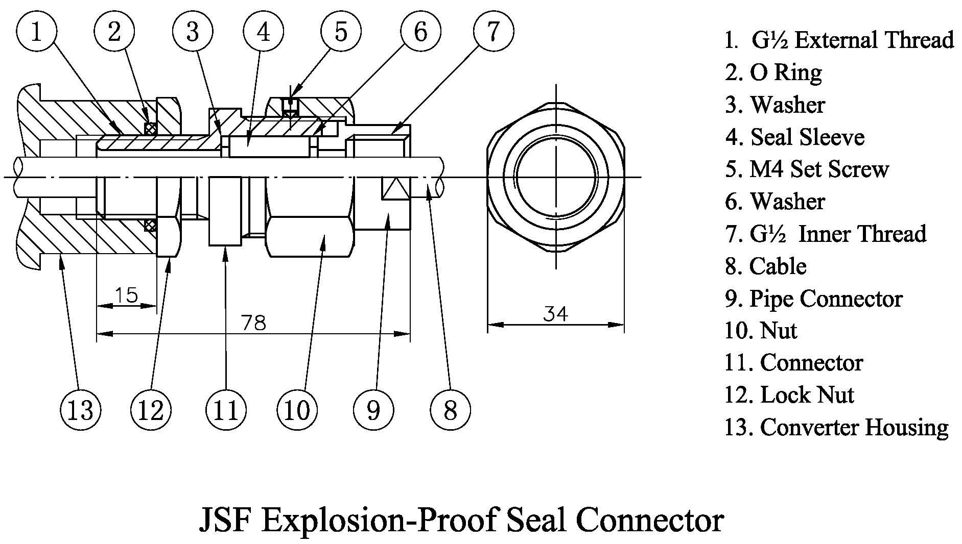
When the cable is leading to the explosion-proof product, a explosion-proof seal connector should be used as shown on the Figure, please refer to the Figure for correct wiring.
1��Ground terminal is available; good ��grounded�� is absolutely necessary in use
2��During operation or/maintenance on site, please always keep in mind of the WARNING ��Don��t open the cover when energized��
3��The out -sleeve diameter of the leading cable is approximately ��8����9��mm��; 3-core-shielded-cable is recommended, they are RVVP3��32��0.2��RVVP3��48��0.2. |
|
|
4��Maintenance must be carried out in the safe area, where no combustible gas exists.
��. Ambient Conditions for Installation:
1��Ambient atmosphere pressure 80kPa -110kPa; temperature -20��C-+60��C, relative humidity ��90%
2��If there are combustible gases or vapors of flammable liquids working around, their explosion class must not be higher than Class II /Grade C; Natural Temperature within T1 - T6 Group; and Installation of the product is only within Zone I or Zone II hazardous area.
3��Listed below is a Table that stipulates the limitations to the Temperature Group Class with the maximum externally-exposed-surface temperature between the explosion-proof product and equipment, and the medium temperature as well. |
Temperature Group Class |
T1 |
T2 |
T3 |
T4 |
T5 |
T6 |
Medium Temperature(��C) |
450 |
300 |
200 |
135 |
100 |
85 |
|
��. Usage:
1��If housing corrosion happens, to replace it promptly
2��Both internal and external ground terminals must be ��earthed�� properly. During maintenance, taking off the Terminal Box Cover must be in power -off condition.
3��The seal ring within the cable-leading connector and the O ring within the cover must be replaced promptly as soon as they are ageing.
4��The connecting between wires and wiring-strips must be in firm and reliable way, meanwhile using insulation sleeve is also necessary , which shall be bent into right angle, to ensue the electrical gap above 4mm
5��Leading cable should be suitable to the on-site possibly corrosive and high temperature enduring conditions.
6��During Terminal Box mounting, please to be sure, do not damage the thread and explosion-proof linkage surface
7��On-site installation, operation and maintenance of the product shall also abide by stipulations related to GB50058-92�� Design Requisition for the Electrical Equipment on Explosion & Fire Hazardous Site�� and GB 3836 .15-2000 |
Settings on the Flow Converter: |
1) Operational Interface:
Display meaning:
3 keys on the Converter panel, they are SET SHIFT and INC respectively
a) Setting key SET: switch working, flow totalized setting and Flow coefficient setting
b) Shifting key SHIFT: adjusting Total Flow Resolution in the total mode; shift the cursor 1- digit to the right in Flow Coefficient mode.
c) Increasing 1 unit key INC: clean the total Flow Display in total mode; in Coefficient mode increasing 1 unit at the cursor position |
|
Display shows 14 characters in total:
FG1 and FG2 are prompt characters: FG1 shows either M or L (M=Cubic Meter L=Liter) FG2 shows P
D1-D5: up-row figure; D6-D12 down-row figure |
|
|
2) Setting: |
(1)Operational Interface:
Varying by Type, Flow Converter operational interface can display as follows:
a) Instant and Total Flow at the same time
b) Instant and Percentage Flow
c) Total Flow
Please refer to chapter 8 Converter Display Mode and examples
|
(2)Settings:
Please read instructions below carefully before setting:
a)The average meter coefficient is shown on the Quality Certificate attached to the Meter ; the Certificate should be well kept for reference; each time, after inspection or calibration, if the coefficient changes, the meter coefficient for the converter should be re-adjusted promptly.
b) The biggest decimal point position for the total flow depends on the meter coefficient, in that case, the user can only move the decimal point to the backward position. During instant flow display, the scanning interval to the instant flow is 1 second , so reading is updated each second . Its decimal point position is locating automatically with full scale readings. |
Meter coefficient range |
The biggest decimal point position & Unit |
|
Full Scale Readings |
Instant Flow decimal point |
0.10000��0.99999 |
XXXXX��XX m3 |
��8 |
X��XXXX |
1.0000��9.9999 |
XXXX��XXX m3 |
8��80 |
XX��XXX |
10.000��99.999 |
XXX��XXXX m3 |
80��800 |
XXX��XX |
100��999.99 |
XXXXX��XX L |
800��8000 |
XXXX��X |
1000��9999.9 |
XXXX��XXX L |
��8000 |
XXXXX |
10000��99999 |
XXX��XXXX L |
|
|
General instructions:
Following parameters can be set for Type FI/TBS/TBL/TBT, varying from Type:
a) Clearing Total Flow (for TBL, void for FI-TBL)
b) Total Flow Resolution adjusting (for TBL; void for FI-TBL)
c) Flow coefficient (applicable to all types)
|
Total Flow Display clearing operation:
In working mode, push SET key to enter Total Flow mode, its operational interface like:
|
|
Under Total Flow setting mode, push INC key (increasing 1 key), Total Flow shows all zero, if push SET key, Clearing is completed ; if Clearing is not required, push INC again, the total flow display resumes, then, push SET key to return to the operational interface without clearing |
Total Flow Resolution adjustment (actually shows Decimal Point position adjustment)
In working mode, push SET key to enter Total Flow mode, its operational interface like Clearing.
The display accuracy of total flow is regarded as the digits kept after the decimal point of total flow displayed.
Higher display accuracy exhibits more precisely the Total Flow, but readings�� overflow happens more often in that case, and the reverse is also true.
In Total Flow setting mode, push SHIFT key (Decimal Point Position Change Key), the Decimal Point
Position of the Total Flow displayed will change accordingly.
Beings Satisfied with the adjusting, then push SET key for operational interface return. |
Flow Coefficient Setting:
In operational mode, consecutively push SET key twice (for TBS; TBT, FI-TBS, FI-TBT); push SET key one time (for TBL, FI-TBL) to enter Flow coefficient, here shows the Operational Interface |
|
Decimal Point display is flashing at the time: push INC (increasing 1 key) to move the Decimal Point to the appropriate digit, push SHIFT key to enter the highest digit setting
The highest digit flashes this time: push INC key to enter the highest effective digit of the Flow Coefficient, push SHIFT for moving to 2nd digit.
Then the 2nd digit flashing, push INC key to enter 2nd digit of the Flow coefficient, push SHIFT for moving to the 3rd
Then the 3rd digit flashing, push INC key to enter 3rd digit of the Flow coefficient, push SHIFT for moving to the 4th
Then the 4th digit flashing, push INC key to enter 4th digit of the Flow coefficient, push SHIFT for moving to the lowest digit
Then the lowest digit flashing, push INC to enter the lowest effective digit of the Flow coefficient, push SET key to save the settings, meanwhile return to operational mode,
Or push SHIFT key to enter Decimal Point position setting (initial Decimal Points is flashing) and re-enter modification
|
3��Application Example:
A Flow Meter with Meter Coefficient K=36.3065(P/L); full- scale- flow Q=40(m3/h) (already being set at ex-works as per Order); display unit: Instant Flow XX.XXX (m3/h),
Total Flow XXXXX.XX (m3)
Setting as follows:
(1) When power is on, the meter opening picture appears, then it enters into the Operational Mode in about 3 seconds. If it is TBS, the display mode shall be ��up-row for Instant Flow, down-row for Total Flow��
(2)In Operational Mode, consecutively to push SET key twice to enter Flow Coefficient Setting, the interface is as shown: |
|
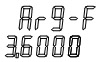
(3)Enter Flow Coefficient, K=36.3065, its 5-digit effective figure=36.307 after round, Push INC once, to set the Decimal Point like XX.XXX, the Meter shows as 36.000, push SHIFT for the highest digit; no change is needed at this digit, push SHIFT key directly for the 2nd digit, no change is needed for the 2nd; Push SHIFT for 3rd digit: push INC key 3 times, the 3rd digit shows 3; push SHIFT key for 4th digit ; no change is needed for 4th; push SHIFT for the 5th digit, push INC for 7 times, the 5th digit is set as 7, the interface appears at the time is shown like this: |
|
(4) Push SET key, to confirm the Meter returns to Operational interface. |
Use & Cares |
1) Use:
(1) Check the installation and wiring of the Flow Meter, make sure no mistaken
(2) Switch the power on
(3) Open the upstream valve for the Flow Meter, then, open the downstream valve smoothly. To ensure the Flow is within the Flow Meter measuring range when the downstream valve is being opened. |
2) Cares
(1) Take care of strong vibration or impact during the Flow Meter operation.
(2) For maintenance, do not take off the Flow Convertor Cover when Power is on
(3)Be sure to prevent the dust from entering the Flow Convertor, if the cover needs to open for wiring.
(4)For remote transmission, if the signal decays through the transmission lines, please try much bigger cable.
|
Transportation & Storage: |
1) During transportation or moving of the Flow Meter (dispatching it to the job-site or returning it for repair), please to keep the Ex-works packing condition that is initially provided by this company.
2) The Flow Meter shall be stored within the room where temperature ranges from 5-40�� and relative humidity does not exceed over 85%, with good ventilation and without corrosive gases.
3) Strictly prohibit from directly taking the Flow Convertor on the Flow Meter for the whole set moving
|
| |
Notice for Ordering:
Cable for the Flow Convertor Output is not included in the delivery. It is customer��s own option. This company offers RVVP metal-shielded-cable with Polyethylene insulation, in 3 specifications as 3��23/0.15, 3��28/0.15; 3��32/0.15 If require, please specify the specification and length during order placing.
|