 |
LWGY Turbine Flow Sensor is a certain kind of flow instrument by measuring flow speed. It is used to measure volumetric flow of fluid which is fully and continuously passing through enclosed pipelines, especially for low-viscosity fluid, being widely applied in petrol, chemical, metallurgical industries and scientific research. |
Features
1)High Accuracy ,±0.5%R in general; ±0.2%R for higher accuracy types
2)Good repeatability; 0.05% for short term; due to its excellent repeatability, very high accuracy can be obtained if it is calibrated often or calibrated on line, so it is the preferable flow meter in trading and business transaction
3)Wide application suitability for water, petrol items (low viscosity) and non-corrosive chemical liquids
4)Pulse frequency signal output; for totalized flow measuring; compatible to computer; no zero drift; strong anti-disturbance ability
5)Wide range-ability: for big and median diameter 10:1; small diameter 6:1 or 5:1
6)Integrated in structure, easy for installation and maintenance
7)Bearings and shafts made of harden alloy with good wear-resisting can be selected in order to increase flow meter life-span for the application in non-lubricated liquids or liquids with particles or corrosion
8)Minimize range-ability for range-low-limit increasing to make the flow meter adaptable in high viscosity fluid measuring; (better attached with on-line calibration axillaries)
9)Multiple outputs and displays at user’s option
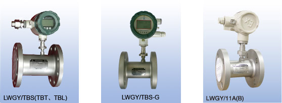
Configuration
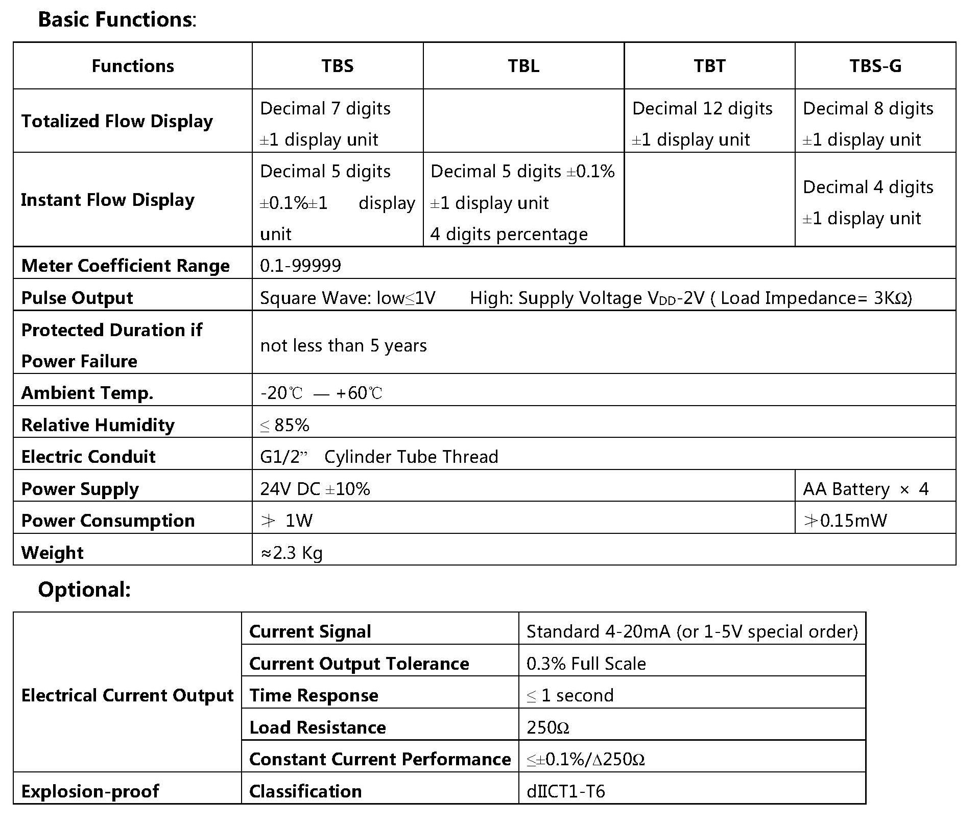
Different Displays at user’s option for different functions:
●Type TBS: Field Instant Flow Rate (5-digit LCD) and Totalized Flow (7-digit LCD)
●Type TBT: Field Totalized Flow (6-digit LCD)
●Type TBL: Field indicating of Instant Flow Rate in Percentage by pointer
●Simple Configuration: with LWF-T Amplifier for pulse output only; LWF-11 for explosion-proof; LWF-11/P for PLC
Product Standard : Q/TDSM 21-2014
Verification Regulation : JJG 1037-2008 Verification Regulation of Turbine Flowmeter
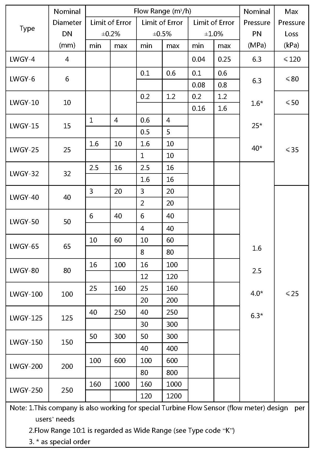
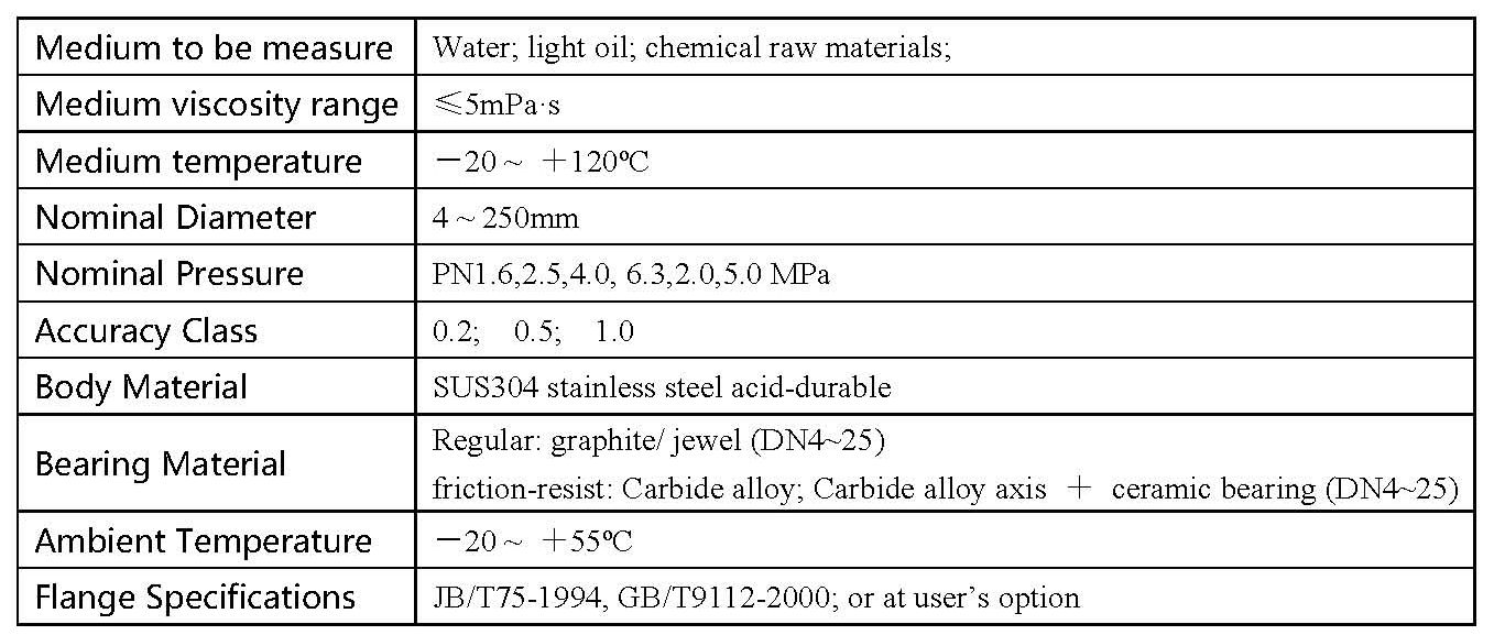
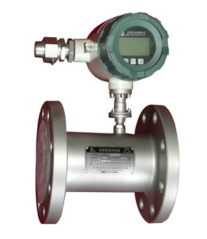
Main Specifications
Product Show
Measuring Part Performance
|
Type Selection
1) Determine Nominal Diameter: as per actual working flow Q (normal flow), by 30%Qmax <Q<80%Qmax to get Qmax; then refer to Main Technical Specification Table by using Qmax to confirm Nominal Diameter;
2)
Determine Fundamental Tolerance (Accuracy): based on actual needs to select ±0.2%; ±0.5%; ±1.0% and others;
3)
Determine Nominal Pressure: as per actual working pressure, base on the principle: actual working pressure < Nominal pressure; to determine nominal pressure;
4) According to determined Nominal Diameter, Tolerance (accuracy) and Nominal Pressure, refer to Code List for Type Selection, to finalize the Flow Meter Type.
Code List for Type Selection
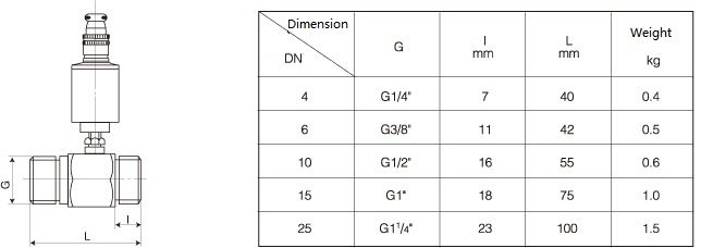
Dimensions & Installation Reference
(Figures shown below for Flow Sensors attached with regular amplifie)
Note: In general, length for Sensor up/down-stream pipeline straight segment requirements are: Up-stream L>10D: Down-stream L>5D.
Dimensions for DN4~25 (PN6.3MPa)
・Dimensions for DN6~25 (PN16, PN25, PN40 MPa, 24°cone connector)
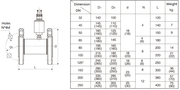
Dimensions for DN32~250 (PN1.6, PN2.5MPa)
Note: Pipeline Flange Standard as per JB/T81-94 (PN1.6, PN2.5)
With Parentheses ( ), it means Flange for nominal pressure 2.5MPa
With *, it means special order
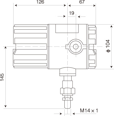
Flow Convertor
Dimensions & Installation Reference
|
|
Totalizer
Amplifier
Type LWF Amplifier
The Turbine rotating signal is being detected, and then the amplifier converts it into electrical signal, which is processed as pulse output to flow calculation meter or computer for displaying and calculating.
Regular Type: LWF-T
Explosion-Proof: LWF-11A, LWF-11B
Explosion-Proof for PLC: LWF-11A/P, LWF-11B/P
|
|
|