 |
Series of vortices will be shed alternatively from both sides of the shedder (that is a cylindrical or triangular bar) when it is inserted in the fluids. Under certain conditions, the frequency of shed vortices should be proportional to volume flow rate. Based on this principle, the flow measurement could be carried out through measuring frequency of vortices by means of vortex flow-meters.
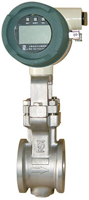
Two versions are available: one has a built-in (integral) converter, and the other is used with a remote converter.
Features:
● Wide application―liquids, gases and steam can all be measured;
● High accuracy and wide flow range;
● Simple structure does not contain any moving parts, and its measuring sensor can not come into contact with fluid. This feature ensures high reliability and easy maintenance;
・
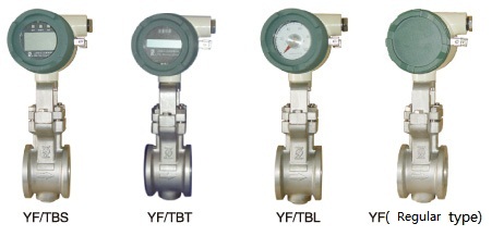
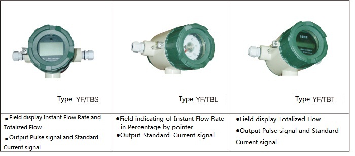
Different Displays at user’s option for different functions:
●Type TBS: Field Instant Flow Rate (5-digit LCD) and Totalized Flow (7-digit LCD)
●Type TBT: Field Totalized Flow (6-digit LCD)
●Type TBL: Field indicating of Instant Flow Rate in Percentage by pointer
Product Standard : Q/TDSM 04-2014
Verification Regulation : JJG 1027-2007Verification Regulation of Vortex-shedding Flowmeter
Product Show:
Main Technical Specifications
| Fluids to be measured |
Liquid, gas or steam |
| Measurable range |
Reynolds Number within 5×10^3 to 7×10^6 |
| Normal Operating Range |
Reynolds number within 2×10^4 to 7×10^6(for nominal sizes 25A to 100A) |
| 4×10^4 to 7×10^6 (for nominal sizes 150A、200A) |
Note: In addition to Reynolds Number, there should be a limit for fluid velocity during measurement; the maximum velocity for liquid is 10m/s, while maximum velocity for gas or steam is 80m/s; besides, minimum velocity is related to density and viscosity of fluids (see “Sizing” section).
Maximum Permissible Errors(within normal operating range)
| Liquid |
±1.0% of indication |
| Gas and Steam |
±1.0% of indication(Flow velocity 35 m/s or less) |
| |
±1.5% of indication(Flow velocity 35~80m/s) |
Note: This table shows the accuracy of Pulse Output version. In case of Analog Output, add up ±0.1% of full scale to the values shown above.
| Repeatability |
±0.2% of indication |
| Span Setting
|
For analog output, a screw-type span adjustment allows span to be adjusted in the following ranges: |
| Liquid : |
| 0-1.1 m/s~0-10m/s (DN25A~100A) |
| 0-1.5m/s~0-10m/s (DN150A、200A) |
| 0-1.7m/s~0-10m/s (DN250A) |
| Gas or Steam : |
| 0-11m/s~0-80m/s (DN25A~100A) |
| 0-15m/s~0-80m/s (DN150A、200A) |
| 0-17m/s~0-80m/s (DN250A) |
Time Constant |
5 s (with analog output converter) |
| Output Signal |
A)Analog: 4 ~ 20 mA DC (2 wire system) |
B)Pulse: Voltage pulse (3 wire system)
Low level: 0 to 2 V
High level: Vs-Vd ( Vs: Input power supply voltage, Vd: Voltage drop , Vd is related to load resistance. Refer to the figure below )
Duty cycles: Approx. 50% |
| C)RS-486协议:MODBUS协议(仅限YF/TBS型) |
Power supply Voltage : Analog Output: 12 to 45 V DC
Pulse Output: 12 to 30 V DC
Process Temperature : -40~300℃
Process Pressure : -0.1MPa to flange ratings
|
Pressure Loss:
At velocity of 10m/s by water, ΔP=0.11 MPa
At velocity of 80m/s by atmospheric air, ΔP=9.1 kPa
(For the relationship between pressure loss and actual flow rate, refer to the figure below )
| Ambient Temperature Limit: |
-40~80℃
-20~60℃ ( Explosion-proof type or with indicator )
-10~60℃ ( With totalizer ) |
| Ambient Humidity: |
5-95%RH |
| Material: |
Body: SCS14 stainless steel
Shedder Bar: SUS329J1 Duplex stainless steel
Converter Case: AC3A-F aluminum alloy |
| Degree of protection of enclosure IP : |
IP65 |
| Explosion-Proof Classification: |
Flameproof enclosure "d" : dIIBT4 |
| Signal Cable: |
Model YF011 cable, used to connect remote detector and converter with its maximum length no more than 20m, and durable temperature within - 40~150℃ |
| Electrical Connection: |
G1/2",cylindrical pipe thread |
| Option Specifications: |
1)Type TBL: Field indicating of Instant Flow Rate in Percentage by pointer,0 to 100% linear division, 250°wide angle indication,only suitable for analog output, 1.5%.
2)Type TBT: Field indicating of Totalized Flow (6-digit LCD),Totalizer value being protected by built-in battery in case of power ,suitable for both analog and pulse output versions
3)Type TBT-G : Field indicating of Totalized Flow , built-in battery,within output
4)Type TBS: Field indicating of Instant Flow Rate (5-digit LCD) and Totalized Flow (7-digit LCD) , suitable for both analog and pulse output versions |
Model and its Suffix Code
旋涡流量计选型计算工具 (点击此处下载)
YF100 Vortex Flowmeter
Type |
Code |
Description |
YF102
YF104
YF105
YF108
YF110
YF115
YF120
YF125
|
…………
…………
…………
…………
…………
…………
…………
………… |
DN25A(without flange)
DN40A(without flange)
DN50A(without flange)
DN80A(without flange)
DN100A(without flange)
DN150A(with flange)
DN200A(with flange)
DN250A(with flange) |
Converter |
-AL………
-AG………
-NN……… |
Integral type (Liquid)
Integral type (Gas or steam)
Remote converter type |
Output signal |
S…………
P…………
N………… |
4~20mA DC(Integral type)
Pulse output(Integral type)
Remote converter type |
Pipe flange joints
comply
with
GB9113RF
GB9119RF |
C1…………
C2………… |
PN1.6MPa
PN4.0MPa |
Style Code |
-CD……… |
Style CD |
Explosion-proof structure |
/JSF |
Flameproof enclosure "d" : dIIBT4 |
Option Specifications |
/ |
|
※ Optional components should be specially ordered.
YFA11 Vortex Flow Converter (Remote type)
Type |
Code |
Description |
YFA11 |
………… |
Vortex Flow Converter |
Measured Fluid |
-L ………
-G ……… |
Liquid
Gas or Steam |
Output Signal |
S…………
P………… |
4~20mA DC
Pulse |
Flow-meter Nominal Size |
-02………
-04………
-05………
-08………
-10………
-15………
-20………
-25………
|
DN25A(without flange)
DN40A(without flange)
DN50A(without flange)
DN80A(without flange)
DN100A(without flange)
DN150A(with flange)
DN200A(with flange)
DN250A(with flange) |
Style Code |
-CD……… |
Style CD |
Explosion-proof structure |
/JSF |
Flameproof enclosure "d" : dIIBT4 |
Option Specifications |
/ |
|
YF011 Signal Cable (Remote type)
Type |
|
Description |
YF011 |
………… |
Signal Cable |
Cable End |
-0 ………
-1 ……… |
Without end finish※
With end finish |
Cable Length |
-05………
-10………
-15………
-20……… |
5m
10m
15m
20m |
Style Code |
-CD……… |
Style CD |
※ One set of end finish is attached. |
Typical Measuring Range
・Water Flow Rate
DN |
NPS |
Measurable Flow Rate
( m^3/h )
|
Normal Operating Flow Rate
( m^3/h ) |
25A |
1 |
0.65~18 |
1.7~18 |
40A |
1-1/2 |
1.3~44 |
2.6~44 |
50A |
2 |
2.2~73 |
3.3~73 |
80A |
3 |
4.3~140 |
4.6~140 |
100A |
4 |
7.5~245 |
7.5~245 |
150A |
6 |
17~540 |
18~540 |
200A |
8 |
34~970 |
34~970 |
250A |
10 |
6~1500 |
6~1500 |
Note: This table is based on standard conditions of 15℃ and 1000 kg/m3 as its density
・Air Flow Rate at selected Pressures
DN |
NPS |
Flow Rate |
Measurable Flow Rate (Nm^3/h) |
0MPa |
0.1MPa |
0.2MPa |
0.4MPa |
0.6MPa |
0.8MPa |
1.0MPa |
1.5MPa |
2.0MPa |
2.5MPa |
25A |
1 |
Minimum |
11.0(19.5) |
15.5(19.5) |
19.0(19.5) |
24.5 |
29.0 |
33.3 |
40.6 |
59.0 |
77.5 |
95.9 |
Maximum |
149 |
297 |
444 |
739 |
1034 |
1329 |
1624 |
2361 |
3098 |
3836 |
40A |
1-1/2 |
Minimum |
21.8(30.0) |
30.8 |
39.3 |
59 |
77.2 |
94.3 |
111 |
149 |
186 |
229 |
Maximum |
357 |
708 |
1060 |
1764 |
2468 |
3171 |
3875 |
5634 |
7394 |
9153 |
50A |
2 |
Minimum |
36.2(38.7) |
51 |
62.4 |
80.5 |
102 |
131 |
161 |
233 |
306 |
379 |
Maximum |
591 |
1174 |
1757 |
2922 |
4088 |
5254 |
6420 |
9335 |
12249 |
15164 |
80A |
3 |
Minimum |
69.8 |
98.4 |
120 |
155 |
197 |
254 |
310 |
451 |
591 |
732 |
Maximum |
1140 |
2266 |
3391 |
5642 |
7892 |
10143 |
12394 |
18021 |
23648 |
29274 |
100A |
4 |
Minimum |
122 |
172 |
219 |
329 |
431 |
526 |
618 |
833 |
1036 |
1277 |
Maximum |
1990 |
3954 |
5919 |
9847 |
13775 |
17703 |
21634 |
31453 |
41274 |
51095 |
150A |
6 |
Minimum |
267 |
440 |
607 |
912 |
1193 |
1458 |
1776 |
2583 |
3389 |
4196 |
Maximum |
4358 |
8659 |
12960 |
21561 |
30163 |
38765 |
47367 |
68871 |
90375 |
111880 |
200A |
8 |
Minimum |
575 |
1009 |
1393 |
2094 |
2739 |
3347 |
3929 |
5301 |
6589 |
7815 |
Maximum |
7792 |
15482 |
23172 |
38552 |
53933 |
69313 |
84693 |
123144 |
161595 |
200046 |
250A |
10 |
Minimum |
1047 |
1814 |
2504 |
3763 |
4922 |
6016 |
7063 |
9528 |
11842 |
14047 |
Maximum |
12049 |
23941 |
35833 |
59617 |
83400 |
107181 |
130968 |
190427 |
249887 |
309346 |
NOTE:
1) All listed flow rates have been converted to standard conditions STP (00C, 1 atm.)
2) All listed pressures are gauge pressures at process temperature of 0℃
3) Maximum flow rate is the lower of values obtained from 80 m/s or Reynolds number
4) The values in parentheses show minimum linear flow rates (Re=20000 or 40000), which
are higher than the minimum measurable flow rates; while the others are the same as theminimum linear flow rates within the normal operating range.
・Saturated Steam Flow Rate at Selected Process Pressure
DN |
NPS |
Flow Rate |
Measurable Flow Rate ( kg/h) |
0.1MPa |
0.2MPa |
0.4MPa |
0.6MPa |
0.8MPa |
1.0MPa |
1.5MPa |
2.0MPa |
2.5MPa |
3MPa |
25A |
1 |
Minimum |
13.4(18.9) |
16.2(20.0) |
20.5 |
24.1 |
27.1 |
30 |
36 |
41 |
49 |
58 |
Maximum |
169.7 |
247.7 |
400 |
548 |
696 |
843 |
1209 |
1575 |
1945 |
2318 |
40A |
1-1/2 |
Minimum |
26.5(29.2) |
32 |
40.6 |
49.0 |
59.2 |
69 |
92 |
114 |
135 |
155 |
Maximum |
405 |
591 |
954 |
1310 |
1662 |
2012 |
2884 |
3759 |
4640 |
5532 |
50A |
2 |
Minimum |
43.9 |
53 |
67.3 |
79 |
89 |
98 |
120 |
156 |
192 |
229 |
Maximum |
671 |
979 |
1580 |
2170 |
2753 |
3333 |
4778 |
6228 |
7688 |
9166 |
80A |
3 |
Minimum |
84.6 |
103 |
130 |
152 |
171 |
189 |
231 |
301 |
371 |
442 |
Maximum |
1295 |
1891 |
3050 |
4188 |
5314 |
6434 |
9224 |
12024 |
14842 |
17694 |
100A |
4 |
Minimum |
148 |
179 |
227 |
273 |
330 |
385 |
514 |
635 |
751 |
865 |
Maximum |
2261 |
3300 |
5324 |
7310 |
9276 |
11230 |
16099 |
20986 |
25904 |
30883 |
150A |
6 |
Minimum |
324 |
401 |
587 |
757 |
915 |
1067 |
1423 |
1759 |
2127 |
2536 |
Maximum |
4951 |
7226 |
11658 |
16007 |
20310 |
24598 |
35250 |
45953 |
56720 |
67624 |
200A |
8 |
Minimum |
679 |
920 |
1348 |
1737 |
2101 |
2448 |
3266 |
4038 |
4778 |
5500 |
Maximum |
8853 |
12920 |
20845 |
28620 |
36315 |
43966 |
63029 |
82165 |
101418 |
120913 |
NOTE:1) Maximum flow rate is the lower of values obtained from 80 m/s or Reynolds number.
2) The values in parentheses show the minimum linear flow rates (Re=20000 or 40000),
which are higher than the minimum
measurable flow rates; while the others might be the same as the minimum linear flow rates within the normal operating range.
旋涡流量计选型计算工具(点击此处下载)
|
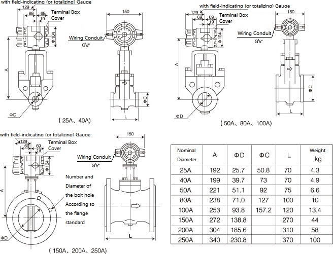
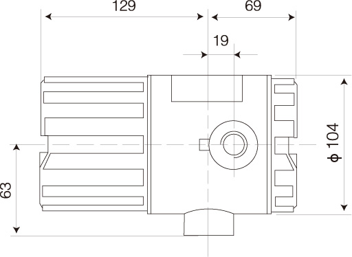
Dimensions & Installation Reference
注:直管段要求:详见“安装说明及图示”
・
Integral type
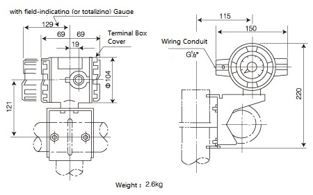
・Remote converter type
Vortex Flow Converter (Remote type)
|
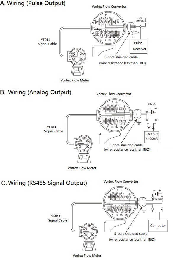
Wiring
Wiring of Integral Type
Wiring of Remote Type
|
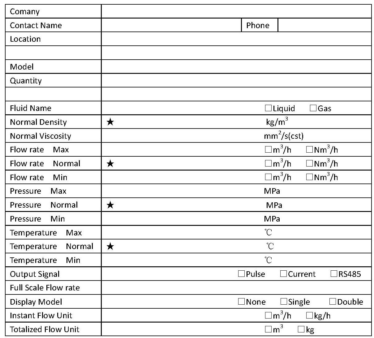
Parameter Table of Model Selection
NOTE:
1.It's required to be filled in which with "★“.
2.Choose in the "□“.
3.For gas flow measurement , the flow unit must be confirm clearly, the flow unit in the working condition is " m^3/h"; the flow unit in the stangdard condition is " Nm^3/h" .
4.The scale flowrate is only corresponded to the analog signal output 4~20mA,for excample ,the scale flowrate "0~100m^3/h" is corresponded to "4~20mA" .
5.Only one flow unit in a flowmeter .
6.Display unit :
● Type TBS: Field Instant Flow Rate ,1m^3/h、0.1m^3/h、0.01m^3/h、1L/h、0.1L/h、0.01L/h , Totalized Flow , 0.1m^3、0.01m^3、0.001m^3、0.1L、0.01L、0.001L
●Type TBT: only display Totalized Flow ,1m^3、0.1m^3、0.01m^3、0.001m^3
The display unit is correlated to DN , the large unit as large DN.
Converter
The Tyoe YF/ converter is usede with YF100 Vortex Flow Meter , testing the flowmeter signal,and transforming, integrating, displaying , and has the power failure protection function。
Converter's function
Main Technical Specifications
1) Basic functions
|
TBS |
TBL |
TBT |
Totalized Flow Display |
Decimal 7 digits ,
±1 display unit |
|
Decimal 6 digits
±1 display unit
|
Instant Flow Display |
Decimal 5 digits
±0.1%±1 display unit
|
Percentage by pointer |
|
Meter Coefficient Range |
1~9999 |
|
1~9999 |
Pulse Output |
Square Wave: low≤1V
High: Supply Voltage VDD-2V ( Load Impedance= 3KΩ
|
Protected Duration if Power Failure |
not less than 5 years |
|
not less than 5 years |
Ambient Temp. |
-10~+60°C
|
Relative Humidity |
≤ 85%
|
Power Supply |
24V DC ±10% |
Power Consumption |
≯2.5W |
≯2W |
≯2W |
Weight |
≈2.5KG |
≈2.8KG |
≈2.3KG |
2) Optional functions
| Electrical Current Output
|
Current Signal |
Standard 4-20mA (or 1-5V special order) |
| Current Output Tolerance |
0.3% F.S |
| Time Response |
≤ 0.5s |
| Load Resistance |
250Ω |
| Constant Current Performance |
≤±0.15%/△250Ω |
RS485 Output |
(only for TBS) |
MODBUS agreement |
Explosion-proof |
Classification |
dⅡBT4 |
3) Dimensions
Totalizer
|
Vortex Flow Meter Installation Description and Indicating
Description |
Indicating |
Pipeline Support :
Install the flow meter in the place with less vibrationIn case of big vibration, pipe support is needed; |
|
Installation Direction:
If pipeline is always fully filled with liquid, pipeline maybe vertically installed, or installed at any angle-directions; |
|
Adjacent Pipeline:
Inner diameter of adjacent pipeline must be slightly bigger than
Inner diameter of YF100 Flow Meter;
Use the adjacent pipeline as below:
25-50mm flow meter: JISSch40(GB G60) and below80-200mm flow meter: JISSch80 (GB G100) and below
|
|
Reducing pipe:
For reducing pipe, to secure straight segment pipe length, at least 5D for its up-stream and 5D for down-stream;
(D: inner diameter of YF100 flow Meter)
|
|
Expanding Pipe:
For expanding pipe, to secure straight segment pipe length, at least 10D for its up-stream and 5D for down-stream;
|
|
Bending Pipe:
For bending pipe, to secure straight segment pipe length, at least 10D for its up-stream and 5D for down-stream;
|
|
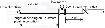
Valve location and Straight segment pipe length:
Valves should be located at flow meter down-stream.Up-stream straight segment length depending on up-stream pipeline conditions
(like expanding pipe,reducing pipe, bending pipe etc, see above; and at least, 5D for down-stream)
If up-stream valve is necessary, to secure the up-stream straight segment pipe Length at least 20D above, 5D for down-stream |
|
|
Pulsing fluctuation flow effect:
If Piston or Roots Air Blower or Compressor is used in gas pipeline, or, Piston or cylinder pump is used in high pressure liquid pipeline, fluid may vibrate;Valve is usually arranged at flow meter down stream; if being located in up-stream is unavoidable, to arrange an Attenuator at flow meter up-stream, such as orifice plate or expansion chamber etc.
|
|
Piston or Cylinder Pump:
To Arrange an energy reservoir at flow meter up-stream to minimize liquid Vibration
|
|
|
Description |
Indicating |
Valve location (pulsing pressure fluctuation caused by T-shape pipe) :
If T-shape pipe is used, to arrange a valve at flow meter up-stream
can avoid pulsing pressure influence; example as shown on the right,
when valve is being closed, fluid is flowing in direction B, no flow
passing through flow meter; however, pulsing pressure is still being
detected, meter zero point is fluctuating; change the valve location to V1’ to avoid what happens
|
|
Pressure measuring hole & Temperature measuring hole:
If pressure measuring is needed, pressure measuring hole shall be arranged at flow meter down-stream about 3.5D to 5.5D
If temperature measuring is needed, temperature measuring hole shall be arranged at pressure measuring point down-stream about 1D to 2D;
|
|
Gasket:
Do not let the Gasket protrude beyond inner pipe, otherwise measuring error occurs; even for clamping-style flow meter , gasket with bolt hole should be used;
If helix gasket (without bolt hole) is used; it needs to be tailor-made by gasket supplier; because standard ones do not fit some flanges. |
|
Thermal Insulation:
Pipes on which assembly-style flow meter or separation-style flow sensor are installed for high temperature fluid transfer must be packed with thermal insulation materials; Never pack the convertor support with thermal insulating materials
|
|
Pipeline cleaning
Before operation, new pipeline or after-maintenance-pipeline need cleaning; wash out rust, sediment, residues and dirt;
During washing, water should be by-passed through by-pass pipe so to prevent flow meter from being damaged;
if by-pass pipe is unavailable, using a short pipe instead of flow meter
|
|
|
|